
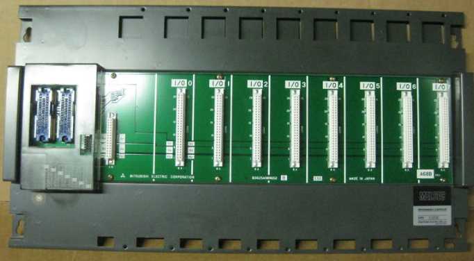
A68B Extended bottom plate MITSUBISHI A68B
Signal transmission device B/NET interface unit for power distribution control equipment.
MITSUBISHI PLC detection, fault diagnosis and display and other procedures.
These procedures are relatively independent, generally in the basic completion of the program design and then add.
MITSUBISHI PLC protection and chain procedures A68B.
Protection and chain is an indispensable part of the program, muust be carefully considered.
It can avoid the control logic confusion caused by illegal operations. Input and output points: 480 points A68B.
Program capacity: 7K step.
Basic command processing speed: 4.4 ~ 5.6us.
Power supply: input DC5V output 2A DC24V/.
Modular: PLC is the basic components of a separate module.
Medium and large PLC used this way. Easy maintenance.
User program storage capacity: it is a measure of how much the user application can store the number of indicators A68B.
Usually in words or K words as units. 16 bit binary number is a word,
Every 1024 words are 1K words. PLC to store instructions and data in words.
General logical operation instructions each account for 1 words MITSUBISHI A68B. Timer / counter,
Shift instruction accounted for 2 words. Data operation instructions for 2~4.
Relay output interface circuit of PLC
Working process: when the internal circuit output digital signal 1,
There is a current flowing through, the relay coil has a current, and then the normally open contact is closed,
Provide load current and voltage MITSUBISHI A68B.
When the internal circuit outputs a digital signal 0, there is no current flowing through it,
The relay coil does not have a current, and the normally open contact is broken off,
A current or voltage that is disconnected from the load MITSUBISHI A68B.
It is through the output interface circuit to the internal digital circuit into a signal to make the load action or not action.
8 slots.
To install the power supply.
For QnA/A series.
Switch volume control is designed to,
According to the current input combination of the switch quantity and the history of the input sequence,
So that PLC generates the corresponding switching output,
In order to make the system work in a certain order.
So, sometimes also known as the order control.
And sequential control is divided into manual, semi-automatic or automatic.
And the control principle is decentralized, centralized and hybrid control three.
Each scanning process. Focus on the input signal sampling. Focus on the output signal to refresh.
Input refresh process. When the input port is closed,
Program in the implementation phase, the input end of a new state, the new state can not be read.
Only when the program is scanned, the new state is read.
A scan cycle is divided into the input sample, the program execution, the output refresh.
The contents of the component image register are changed with the change of the execution of the program.
The length of the scan cycle is determined by the three.
CPU the speed of executing instructions.
Time of instruction.
Instruction count.
Due to the adoption of centralized sampling.
Centralized output mode.
There exist input / output hysteresis phenomena, i.e., the input / output response delay.
System program memory for storing system proggram,
Including management procedures, monitoring procedures, as well as the user program to do the compiler to compile the process of interpretation A68B.
Read only memory. Manufacturers use, content can not be changed, power does not disappear.
Related supply information